DAC Worldwide is a world leader in technical training solutions for industrial skills including a full range of training/assessment systems, industrial cutaways, & custom scale models.
T (800) 662 5877
Email: sales@dacworldwide.com
DAC Worldwide
601 Heron Drive, Swedesboro, NJ USA 08085
Mechanical & Civil Engineering | Advanced Laboratory Training
Solutions
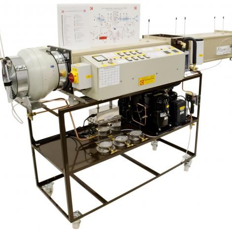
Air Conditioning Laboratory Unit - A660
PA Hilton's Air Conditioning Laboratory Unit (A660) is a complete, upgradeable, instrumented air conditioning laboratory unit mounted on a steel frame with casters. Upgrades may be added at any stage in the unit’s long life to spread the investment costs.
The base unit comprises a variable speed radial acting axial flow fan discharging into a 250mm square duct with steam humidifier, electrical pre-heaters, direct expansion cooling coil/de-humidifier, electrical re-heaters, and orifice plate for airflow measurement. Air-cooling is provided by vapour compression refrigeration system with pressure, temperature, and refrigerant flow measurement. This allows the construction of a full cycle diagram and the balancing of refrigerant system energy balance against the airside energy transfer.
- Psychrometric condition measured before and after each process by high precision wet and dry bulb sensors with 0 to 100% RH measurement capability.
- Airflow is adjustable to at least 0.14m3/s.
- Switchable heating up to 4kW.
- Switchable steam injection up to 5kW electrical equivalent.
- Cooling is by a fully instrumented vapour compression cycle with nominally 2kW capacity.
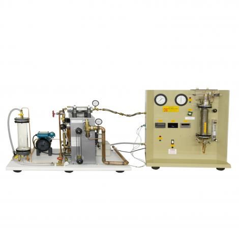
Rankine Cycle Steam Turbine - S220
PA Hilton's Rankine Cycle Steam Turbine (S220) consists of a fired steam generator for wet or superheated steam, a condensing unit with air ejector, and a closed feed water system.
The unit is supplied as two complimentary modules. An independently certified electric boiler with safety valve, automatic control system, and fail-safe pressure switches provides steam at up to 8 Bar gauge to a solenoid valve. This in conjunction with an optical sensor limits the maximum turbine speed to a safe level. Steam flow to the turbine can be throttled by a hand valve and the boiler, turbine inlet, and condenser pressures are indicated on gauges.
The impulse turbine is driven by a convergent divergent nozzle and turns a brake wheel with speed sensor and digital indicator, allowing true shaft power to be determined. An optional electrical power generator is also available for demonstration purposes.
The turbine exhausts into a condenser and this passes water to a similar water reservoir. The reservoir connects to a boiler feed pump. Like a full-size real power plant, the condenser operates at sub-atmospheric pressure and the unit incorporates an air extraction system. The boiler feed pump and non-return valves to the boiler complete the full Rankine cycle.
Instrumentation includes all relevant system pressures, system temperatures, cooling water flow rates, turbine speed, and brake load. A combination of digital and analogue displays show the recorded parameters.
- Boiler:
- Independently certified electric boiler with automatic control
- Pressure switches
- Fail safe pressure cut out and large capacity relief valve
- Turbine:
- Single stage, axial flow impulse (De Laval) turbine on a vertical shaft mounted in corrosion resistant sealed ball bearings.
- Convergent-divergent nozzle discharges at 20° to plane of turbine rotation
- Rotor has blades with 40° inlet and discharge angles.
- Rotor Ø50mm.
- Maximum turbine speed 40,000 rpm.
- Water cooled Condenser: Condenses turbine exhaust steam allowing heat rejection from the system to be measured.
- Feed Water Reservoir: Collects condensate from the condenser for return via the feed pump to the boiler.
- Feed Pump: low volume flow pump.
- Flow Meters: For condenser cooling water. Allows measurement of heat rejection from the condenser.
- Digital Thermometer: 0.1°C resolution, with multi-way selector switch for all relevant temperatures
- Pressure gauges: For all relevant system pressures.
- Turbine Tachometer: Digital display and over speed cut out.
- Turbine brake load: Digital indicator.
Heat Transfer Service Unit + Radial Heat Conduction Module - H112/H112B
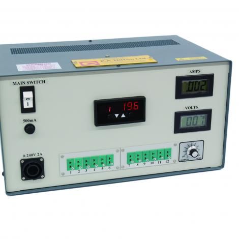
PA Hilton's Heat Transfer Service Unit (H112) is a fully-instrumented bench top Heat Transfer Service Unit providing regulated and adjustable AC power for all of the optional modules plus a number of auxiliary power outlets.
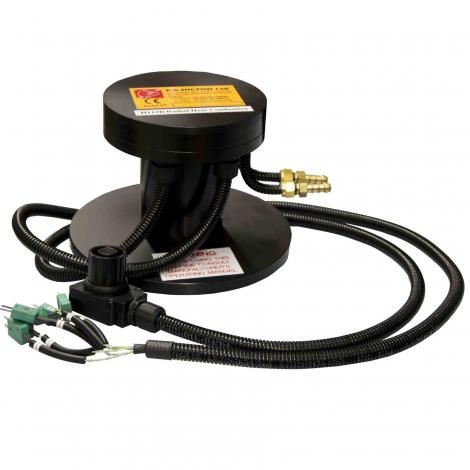
The Radial Heat Conduction Module (H112B) is a small-scale accessory designed to experimentally investigate the basic principles of radial heat conduction and to allow the thermal conductivity of the solid metal disc to be determined.
The unit includes instrumentation that is common to all modules, including a 12 point digital temperature indicator and digital current and voltage meter. Where appropriate, additional instrumentation is supplied with the various optional modules.
The range of optional modules currently include convection, conduction (steady state and transient), radiation, perfect gases, thermodynamic properties of fluids and solid materials, enhanced methods of heat transfer, thermoelectric heat transfer, boiling and condensing heat transfer and a closed cycle heat engine. However, the range is continuously being expanded.
Internal electronic and mechanical safety devices allow for unsupervised operation by students. Optional data acquisition is available for attachment to this unit.
- Coated Steel Console
- 0…240Vac, 2A supply
- 8A Miniature circuit Breaker (MCB)
- 12 temperature inputs
- 0…999.9°C, 0.1°C resolution
- Residual Current Circuit Breaker (RCCB)
An insulated, 110mm diameter brass disc 3.2mm thick is heated in its centre by a nominal 100W heater (operating at 240v ac maximum) which is fitted with a high temperature limit switch. The power supplied to the heater is controlled and measured by the Heat Transfer Service Unit.
The periphery of the disc is cooled by water passing through a copper tube bonded to the disc.
Six type K thermocouples are positioned at 10mm radial increments from the heated centre to the periphery. All six thermocouples plug directly into the Heat Transfer Service Unit and temperatures are displayed on its digital panel meter.
- Heated Disc. Material: Brass, Ø110mm.
- Brass Core: Ø14mm.
- Disc Thickness: 3.2mm.
- Radial interval of Thermocouples: 10mm
- H112A: Linear Heat Conduction Module
- H112C: Laws Of Radiant Heat Transfer/Heat Exchanger Module
- H112D: Combined Convection And Radiation Module
- H112E: Extended Surface Heat Transfer Module
- H112F: Radiation Errors In Temperature Measurement Module
- H112G: Unsteady State Heat Transfer Module
- H112H: Thermal Conductivity Of Liquid And Gases Module
- H112J: Perfect Gas Laws Demonstration Module
- H112M: Marcet Boiler
- H112N: Thermal Conductivity Of Building Material Unit
- H112P: Free And Forced Convection From Flat, Pinned And Finned Plates
- H112Q: Thermoelectric Heat Pump
- H112R: Stirling Engine
- H112S: Boiling Heat Transfer Module
Combustion Laboratory Unit (Gas Burner Fitted) - C492
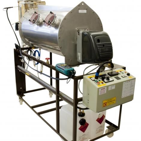
PA Hilton's Combustion Laboratory Unit - Gas Burner Fitted (C492) enables students to study many aspects of combustion and burner operation using burners typical of those used commercially.
A gas burner is fitted as standard. The unit is frame mounted, is fully instrumented, and requires only a conventional single-phase electrical supply, cooling water, and the chosen fuel.
As a purpose-built training unit, it is designed for supervised student operation by including several safety features. A handheld digital gas analyser supplied allows the O2 content of the flue gas to be determined and this in turn allows calculation of the air/fuel ratio, excess air, and combustion efficiency.
For advanced students or research, an optional high specification gas analyser is available that allows investigation of CO, NO, and SO2 in addition to the standard analysis.
The unit will be of wide interest to all those concerned with the combustion of fuels and energy conservation, from the burner maintenance technician to research and test engineers.
- Frame: Powder coated 25 mm mild steel angle frame with 16 swg shelves.
- Chamber: Stainless steel combustion chamber, approximately Ø450 mm ID, Ø500mm OD x 1000 mm long, with four 100 mm quartz glass windows.
- Chamber and end plate water cooled, front plate has 80mm thick insulation and burner mounting studs.
- Gas Burner: Package burner with integral fan and control box, and multibloc valve. Operates on natural gas (methane) or LPG gases at heat rates up to 100kW approx. (depending on fuel).
Heat Exchanger Service Unit - H102
PA Hilton's Heat Exchanger Service Unit (H102) is a bench-mounted panel with an integral electrical console that provides services for any of the 11 available heat exchangers.
Temperature controlled hot water is provided from an electrically heated tank by a continuously rated fixed speed pump. Mains cold water is pressure regulated. Hot and Cold flow is controlled and measured using variable area flowmeters. The optional heat exchangers are connected to the service unit using non-drip, self-sealing couplings.
Electrical safety is provided by double pole overload and earth leakage circuit breakers. The hot water system is equipped with a safety temperature limiting device.
The standard instrumentation consists of up to 12 type T thermocouples, displayed on a digital panel meter, and two flowmeters for hot and cold fluids. These enable all relevant heat transfer calculations to be made. Optional Heat exchangers in some cases add other measurement configurations.
An optional Computerised Data Acquisition Upgrade is also available to allow all available parameters to be recorded on a computer in real time.
- 11 x Essential Heat Exchangers available
- 12 Temperature inputs
- Hot water flow rate: 4…50 gm/s
- Cold water flow rate: 4…50gm/s
- Digital Temperature Indicator: 0.1°C resolution
- Water Heater: 3kW immersion heater
- Water heater protection: 80°C maximum thermostat
- H102A - Concentric Tube Heat Exchanger
- H102B - Plate Heat Exchanger
- H102C - Shell & Tube Heat Exchanger
- H102D - Jacketed Vessel with Coil and Stirrer
- H102E - Extended Concentric Tube Heat Exchanger
- H102F - Extended Plate Heat Exchanger
- H102G - Water/Water Turbulent Flow Heat Exchanger
- H102H - Coiled Concentric Tube Heat Exchanger
- H102J - Recycle Loops
- H102K - Film and Dropwise Condensation
- H102M - Water to Air Heat Exchanger Module
Bench Top Cooling Tower - H893
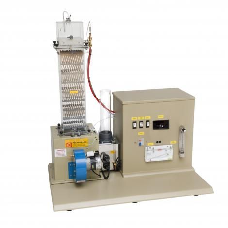
PA Hilton's Bench Top Cooling Tower (H893) has been designed to meet the demand for a compact cooling tower which clearly demonstrates all the processes found in a full size forced draught cooling tower and behaves in a representative manner.
Supplied with standard column B, a number of additional columns are available as optional extras to cope with a wide variety of educational needs in the study of Thermodynamics, Heat and Mass Transfer, Refrigeration, and Air Conditioning.
Warm water is pumped from the load tank to the column cap where its temperature is measured. The water is uniformly distributed over the top packing deck and, as it spreads over the plates, a large thin film of water is exposed to the air stream. During its downward passage through the packing, the water is cooled, largely by the evaporation of a small portion of the total flow. The cooled water falls from the lowest packing deck into the basin, from where it flows past a thermocouple and into the load tank where it is re-heated for re-circulation.
Due to evaporation, the level of the water in the load tank slowly falls. This causes the float operated needle valve to open and transfer water from the make-up tank into the load tank. Under steady conditions, the rate at which the water leaves the make-up tank is equal to the rate of evaporation, plus any small airborne droplets in the air discharge
Air from the atmosphere, pre-heated by external means if desired, enters the fan at a rate controlled by the intake damper setting. The fan discharges into the distribution chamber and the air passes wet and dry bulb thermocouples before it enters the packed column. As the air stream flows through the packings, its moisture content increases and the water is cooled. On leaving the top of the column the air passes through the droplet arrester, which traps most of the entrained droplets and returns them to the packings. The air is then discharged to the atmosphere via the air measuring orifice and further wet and dry bulb thermocouples. All of the foregoing may be observed through the transparent structure of the column.
All temperatures are indicated by a digital temperature indicator and thermocouple selector switch.
- Column Dimension: 150(L) x 150(W) x 600(H) mm
- Number of Decks: 8
- Number of plates per deck: 10
- Surface area of Packing: 1.19m2
- Constructed in Impact Resistant Plastic
- Load tank with 0.5 and 1.0 kW heaters
- Float level control
- Make-up tank
- Bronze circulating pump
- Air fan
- Electrical control panel with digital temperature indicator
- Column B packing Density: 100m2 per m3
Refrigeration Laboratory Unit - R715
PA Hilton's Refrigeration Laboratory Unit (R715) is a fully-instrumented refrigerant R134a vapour compression refrigerator and has been designed to enable students to safely study the cycle in detail.
The vapour compression refrigeration cycle is used in many industrial, medical and domestic situations throughout the world. Air conditioning, food and medical preservation and transport all rely on the use of refrigeration plant. It is essential therefore that student engineers intending to design or utilise such plant are fully aware of the parameters affecting the performance of the vapour compression refrigeration cycle.
A refrigerator is defined as a machine whose prime function is to remove heat from a low temperature region. The most common type of refrigerator or heat pump operates on the Vapour Compression Cycle and requires a work input.
The Hilton Refrigeration Laboratory Unit R715 has a belt driven compressor, electrically heated evaporator, thermostatic expansion valve, and water cooled condenser. Operating parameters can be varied by adjustment of condenser cooling water flow and electrically heated evaporator supply voltage.
Components have a low thermal mass resulting in immediate response to control variations and rapid stabilisation. Instrumentation includes all relevant temperatures, condenser pressure, evaporator pressure, refrigerant and cooling water flow rates, evaporator and motor power, motor torque, and compressor speed.
- Panel: High quality GRP.
- Refrigerant: R134a.
- Digital Thermometer: 6 way type K indicator with 0.1°C resolution.
- Wattmeter: Allows measurement of the power input to either evaporator or motor.
- Voltage Controller: To vary evaporator load.
- Variable Area Flowmeters x 2: Variable area types to indicator R134a and H20 flow rates.
- Pressure Gauges x 2: to indicate R134a pressure in evaporator and condenser.
- Spring Balance and Tachometer: Together allow measurement of power required to drive the compressor.
- Expansion Valve: Thermostatically controlled type.
- Evaporator: Electrically heated device.
- Compressor: (Internally mounted) Twin cylinder belt driven unit.
- Safety:
- Condenser pressure and evaporator heater temperature limited by automatic cut-outs.
- All electrical components connected to common earth.
- Unit protected by miniature circuit breaker and residual current circuit breaker.
Ventilation Trainer - B500
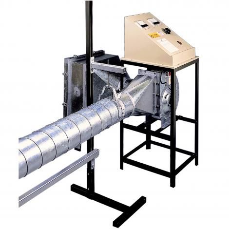
PA Hilton's Ventilation Trainer (B500) is a realistically-scaled ventilation training unit capable of enabling students to study both basic airflow and fluid mechanics, as well as the more complex process of commissioning and balancing a multi-ducted air distribution system.
The unit consists of a forward curved, variable speed centrifugal fan and integral control console together with a rectangular air intake and filter holder. The fan has a supply pressure of up to 890N/m2 and a flow rate of up to 0.8m3/s depending upon the blockage factor. The fan discharges directly into a 200mm dia. galvanised steel duct and this connects directly to the distribution ductwork.
Sufficient components are supplied with the unit to enable parallel branch and line balancing experiments to be undertaken. A minimum of 6 air supply points are provided that may be balanced on the assembled unit to supply a range of airflows. A portable manometer, pitot static tube, and handheld anemometer allow a large range of experiments to be undertaken.
- Fan Unit: Motor power 0.75kW (approx.) on load. Starting load is greater.
- Fan supply pressure of up to 890N/m2, flow rate of up to 0.8m3/s depending upon the blockage factor.
- Fan discharge directly into a 200mm dia. galvanised steel duct.
- Control Console: Analogue Voltmeter, analogue Ammeter, variable Transformer, combined miniature circuit breaker and Main Switch, Internally mounted.
- Epoxy coated steel frame housing the fan unit.
- Ductwork Galvanised steel.
- A combined vertical (Range 0-2000 N/m²) and inclined (Range 0-200 N/m²) manometer.
- Unit supplied with 305mm x 4mm diameter pitot static tube and spare fluid.
- A battery powered rotating vane anemometer with digital readout. Range approximately 0-30m/s.
- Internally fitted 30mA Residual Current Circuit Breaker gives high degree of protection to operator from electrical shock.
- All rotating components covered when filter and holder are in position.
Air and Water Heat Pump - R833
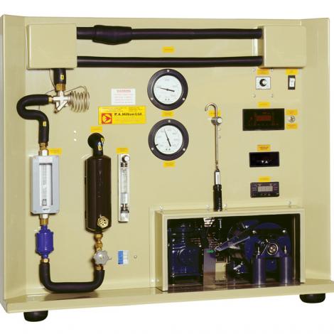
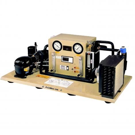
PA Hilton's Air and Water Heat Pump (R833) enables students to plot the pressure enthalpy and performance graphs as conditions are changed, so enhancing their understanding of heat transfer theory.
The vapour compression cycle is the most common form of refrigeration, transferring heat from the area being cooled to a higher temperature region. Heat Pumps use this effect to recover heat at a useful temperature for heating or some other process by upgrading low grade ‘free’ heat e.g. from ambient air or water.
Due to concerns about the effects of global warming, awareness of energy conservation must increase and heat pumps are an effective method of reducing energy consumption. Hence an understanding of their operation is relevant to many engineering disciplines.
R134a refrigerant vapour is compressed in a hermetic compressor and then flows to a water cooled condenser. Heat is transferred to cooling water and the refrigerant vapour is condensed to a high pressure liquid which passes through a thermostatic expansion valve.
A switch allows the user to direct the flow of the expanding vapour to either an air or water source evaporator where heat is extracted or the cycle is repeated. In order to recover waste heat from the compressor, the condenser cooling water also passes through a heat exchanger in the compressor casing. All components are mounted on a high quality ABS panel and base.
Instrumentation includes pressure gauges, flowmeters, thermocouples, and wattmeter, allowing students to record all of the relevant parameters to create performance curves and refrigerant cycle diagrams.
- Panel: High quality ABS.
- Controls: Operating parameters may be varied by manual adjustment of the evaporator and condenser water control valves, and selecting the air or water source evaporator by panel mounted switch.
- Gauges x 2: Evaporating and condensing pressures
- Multi-point Digital Temperature Indicator: 9 type K thermocouples. Resolution 0.1K
- Flowmeters x 3: For condenser cooling water and evaporator water flow rates and R134a flow rate.
- Digital Wattmeter for compressor electrical energy.
- Safety Features:
- Condenser high pressure switch and compressor thermal overload switch.
- Residual current circuit breaker
- Combined double pole main switch and overload cut out.
- All electrical components connected to common earth conductor.
Steam to Water Heat Exchanger - H931
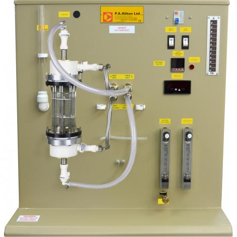
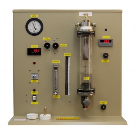
PA Hilton's Steam to Water Heat Exchanger (H931) is designed to provide visual and quantitative results related to heat transfer in shell and tube type water cooled condensers.
Three interchangeable manifolds allow investigation of single, double, or four pass cooling water flow through the condenser tubes.
The unit is self-contained and designed for bench top use having its own steam generator and condenser tubes housed in a single thick walled glass cylinder.
Instrumentation monitoring the cooling water flow rate, temperature and pressure drop through the tubes allow an interesting and important range of experiments to be conducted. The unit is easily controlled and stabilises quickly allowing many different conditions to be investigated in a single laboratory period.
- Panel: High quality ABS
- Digital Thermometer: Resolution 0.1°C.
- Differential Pressure transducer and Display.
- Flow meters x 2: 10 to 90 cm³ s-1 and 1 to 12 g s-1.
- Pressure Gauge: Range: - 100 to +100 kN/m2.
- Safety Features:
- Steam chamber pressure relief valve, pressure switch and heater high temperature cut out.
- All electrical components earthed and fuse.


