DAC Worldwide is a world leader in technical training solutions for industrial skills including a full range of training/assessment systems, industrial cutaways, & custom scale models.
T (800) 662 5877
Email: sales@dacworldwide.com
DAC Worldwide
601 Heron Drive, Swedesboro, NJ USA 08085
Electrical Engineering & Automotive Technology | Advanced Training
Solutions
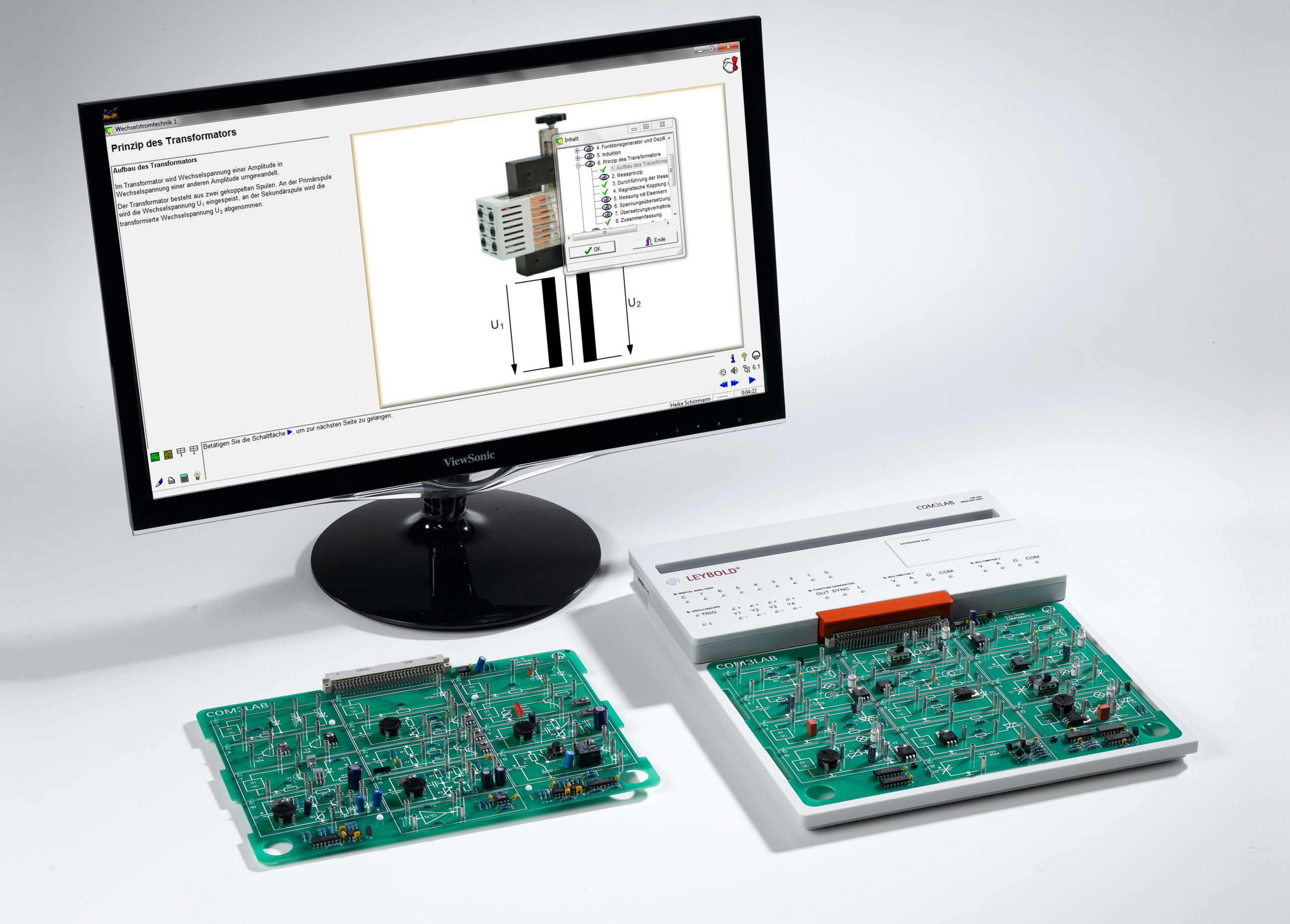
COM3LAB: Multimedia Lab for Electronics & Electrical Engineering - 700 020
COM3LAB is a multimedia-based learning software for vocational and advanced training in the technical and engineering fields. The focus is on vocational training in electrical engineering and automotive technology.
The interactive learning program starts with a theoretical introduction followed by at least one topic-related, practical experiment. The COM3LAB self-assessment test ensures that the course content is absorbed and consolidated.
A wide variety of different COM3LAB courses are available for fundamental and advanced topics in the fields of electrical engineering and automotive technology.
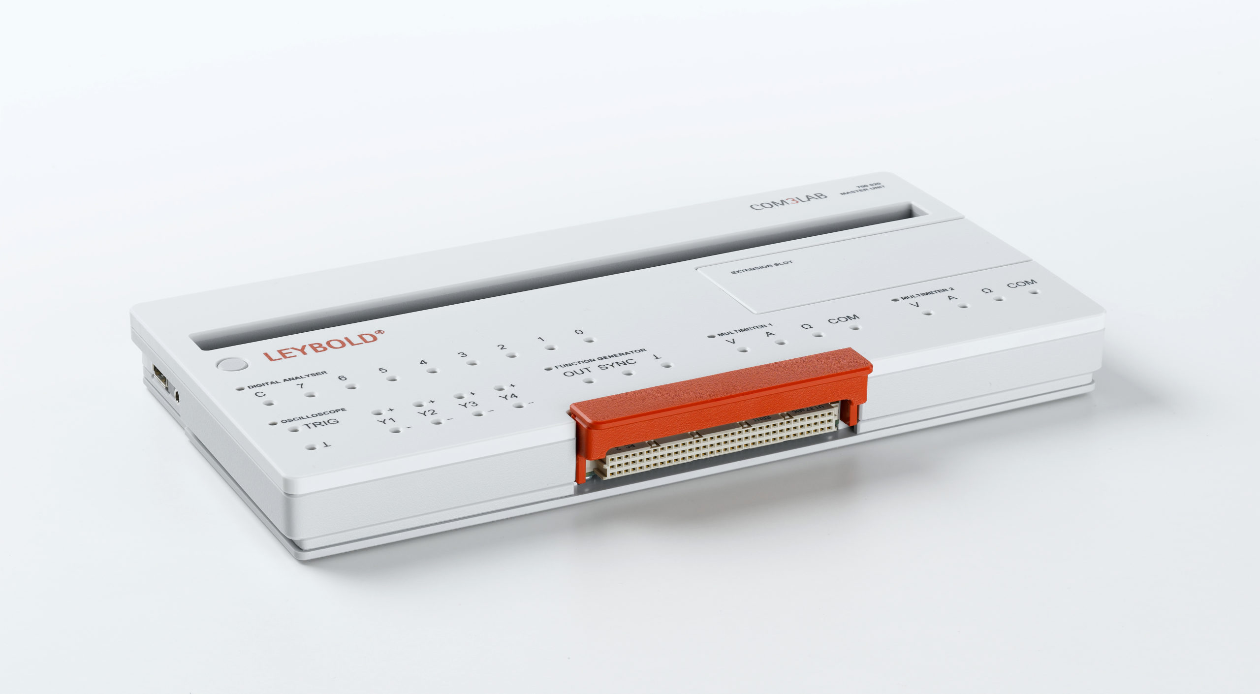
The COM3LAB Master Unit (700 020) is a multifunctional, compact, measuring interface. It is used for the operation and power supply for the COM3LAB multimedia experiment boards and as an independent measuring laboratory. The Master Unit is connected to the PC via a USB Port, WiFi or Ethernet for the recording of measurements and for remote control of it's built-in functions. The Master Unit can be quickly attached to an experiment board via the experiment board carrier. It's clear and structured design results in easy operation.
The COM3LAB software can be downloaded from www.LD-DIDACTIC.de free of charge or obtained on DVD (700 OOCBT). For each COM3LAB multimedia course there is an electronic, interactive instruction manual. The contents of the manual are dependent on the topic and are tailored to the hardware. The operation and function of the manuals are identical for all courses. The 32-bit user interface, into which the interactive manual, the virtual lab and the tools are integrated, also remains the same for all courses.
- Two digital multimeters:
Voltage: AC / DC / AD + DC 2/20 V
Current: AC/DC 0,2/2 A
Resistance: 2/20/200 kΩ, 2 MΩ
Autoranging for all measurement ranges - Digital Function generator:
digitally generated signal types
Sinusoidal, square-wave, triangular, DC
0.5 Hz...100 kHz
Max. ±10 V, max. 250 mA - Digital 4-channel oscilloscope:
4 differential inputs
Sampling rate: 1 MSamples per channel
Resolution: 12 Bit per channel
Memory depth: 1 K Samples per channel - Digital analyzer:
9 digital inputs, TTL-compatible
Sampling frequency: 200 Hz to 2 MHz
Triggering on any combination of the input statuses
Memory depth 2048 words with 9 Bits
- Electronic Components I (700 1501)
- Electronic Components II (700 1601)
- DC Technology I (700 1101)
- DC Technology II (700 1201)
- AC Technology I (700 1301)
- AC Technology II (700 1401)
- Digital Technology I (700 1701)
- Digital Technology II (700 1801)
- Power Electronics I (700 2101)
- Power Electronics II (700 22)
- Three-Phase Technology (700 2401)
- Electrical Machines I (700 2501)
- Automation and Bus Technology (700 3101)
- Electro Pneumatics (700 3501)
- Photovoltaics (700 5301)
- Automotive Electrics (700 6101)
- Automotive Sensor Technology (700 6201)
- Automotive Data Buses (700 6301)
- Automotive Digital Technology I (700 6401)
- Automotive Digital Technology II (700 6501)
- Digital Communication Technology (700 7301)
- Modem Technology (700 7401)
- Telecommunication Lines (700 7501)
- Operational Amplifier (700 8101)
- Control Technology I (700 8201)
- Control Technology II (700 83)
- Sensor Technology (700 8401)
- Protoboard II (700 9101)
- Microcomputer Technology II (700 20)
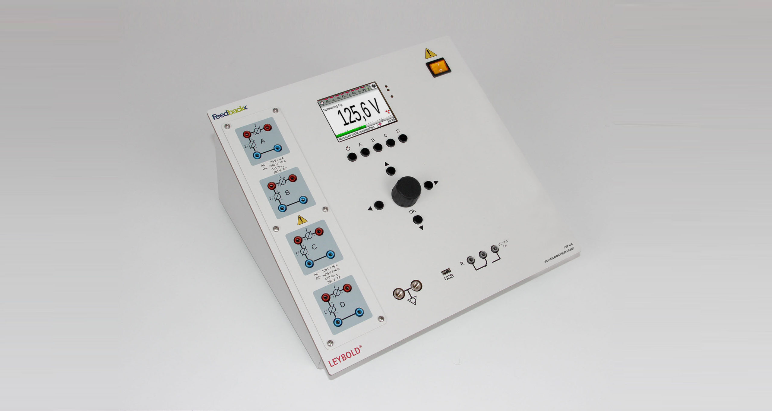
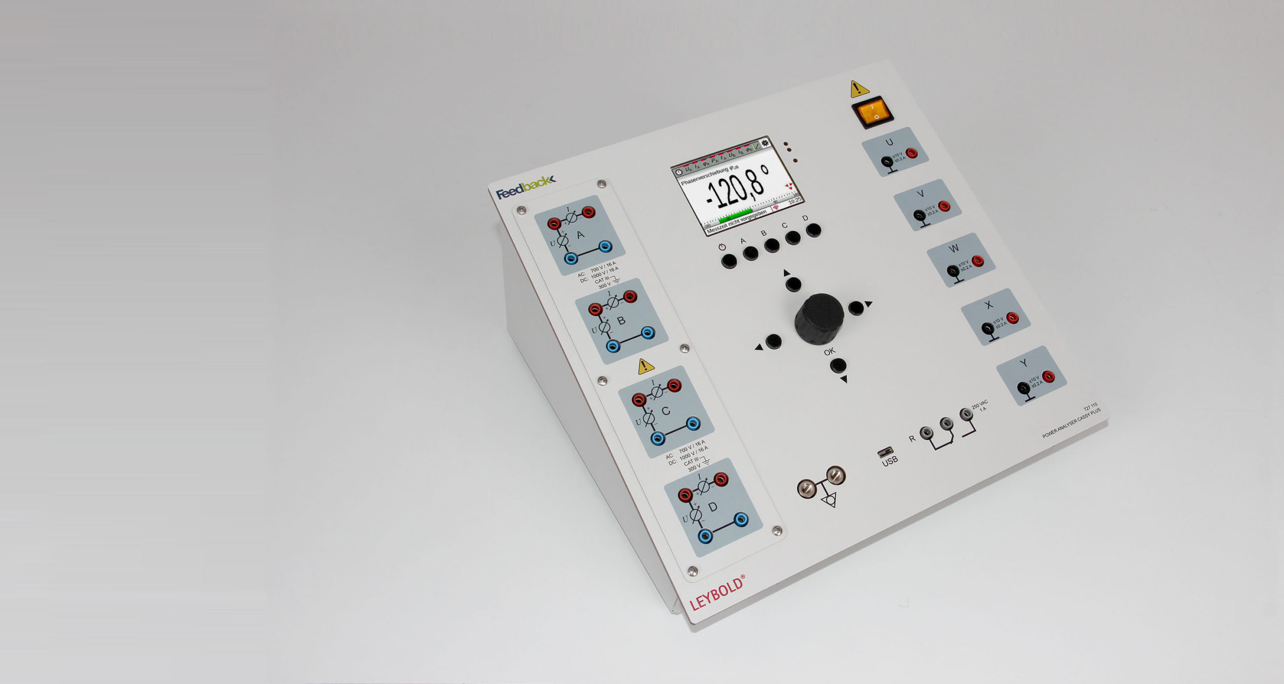
Power Analyser CASSY - 727 100
The Power Analyser CASSY is a combination of an isolated and differential oscilloscope, multimeter, wattmeter, energy analyser, and recorder.
The Power Analyser CASSY is designed for demonstration and laboratory experiments in the following areas of application:
Energy networks
- Voltage and frequency stability
- Load behaviour of networks
- Effect of harmonics
Electrical machines
- Inrush current from transformers and machines
- Transformation ratio of transformers
- Efficiency of machines
Power electronics
- Rectifier
- DC/DC converter
- DC/AC converter
- Frequency converter
- Filter
- Simultaneous measurement of U, I, φU, φI, f and P
- instantaneous values U, I and P
- averaged values U, I and P
- RMS values (AC+DC) U and I
- fundamental wave filters
- Delta connection adjustment
- Measuring accuracy U,I is at 0,5%.
- Frequency response voltage: 100 kHz 3 dB 250 V
- Frequency response current: 40 kHz 3 dB at 10 A
- Universal connection options
- via USB connection with PC or laptop
- via WiFi with the school network or setting up an access point
- Automatic or manual range selection
- Supports the prize-winning measurement software CASSY Lab 2 for computer-aided measurements and simple to highly complex evaluations:
- Electrical power calculation S, P, QC and QL
- Electrical work WS, W and WQ
- Resistance calculation R, Z, XC, XL, G, Y BC and BL
- Positive sequence component, negative sequence component and zero sequence component in 3-phase systems
- Time derivative, integral over time, FFT analysis, mean value, histogram, and modelling
- Drivers for LabVIEW and MATLAB available
- Possibility of direct manual operation of the device by means of a rotary selector with cursor keys direct value readings on 9 cm backlit display
- Display of up to 24 measured values on one display
- Display of all values for each channel
- Display of all values in tabular form
- Display of measured values in a diagram
- Display of a vector diagram
- Wireless connection to the CASSY app via WiFi for experimentation with tablets and smartphones (iOS, Android and Windows)
- Measuring instrument category CATIII 300: allows the use of the measuring instrument for tests with safety extra-low voltage (SELV) via 3-phase systems with or without neutral conductor, up to testing in power electronics, e.g. DC link voltage of 700 V DC
- Real-time processing in the device enables comprehensive network analysis in the three-phase networks, which are displayed directly on the device in the vector diagram
DISPLAY & OPERATION
- Graphic display: 9 cm (3,5“), QVGA, colour, light (adjustable up to 400 cd/m²)
- Operation: Button and incremental encoder with button
INPUTS & OUTPUTS
- Inputs: 4 isolated measurement channels CATIII 300, each with I and U measurement (max. 8 usable simultaneously)
- Input A-D: U and I connection via 4 mm safety sockets
- Measurement range U: 25/70/250/700 VAC ±36/±100/±360/±1000 VDC
- Measurement range I: 0.7/1.6/7/16 AAC ±1/±2.5/±10/±16 ADC
- Sampling rate: max. 1.000.000 values/s per channel for U, max. 500.000 values/s for I
GENERAL
- Data storage: integrated micro SD card (4 GB) for more than a thousand measurement files and screenshots
- Remote access: full remote access and distribution of measurement data
- WLAN: as access point or client
- USB port: Type C
- Dimensions: 300 mm x 300 mm x 180 mm
- Weight: 3,7 kg
Basics of Automobile Electrical Engineering - 727 520KOF
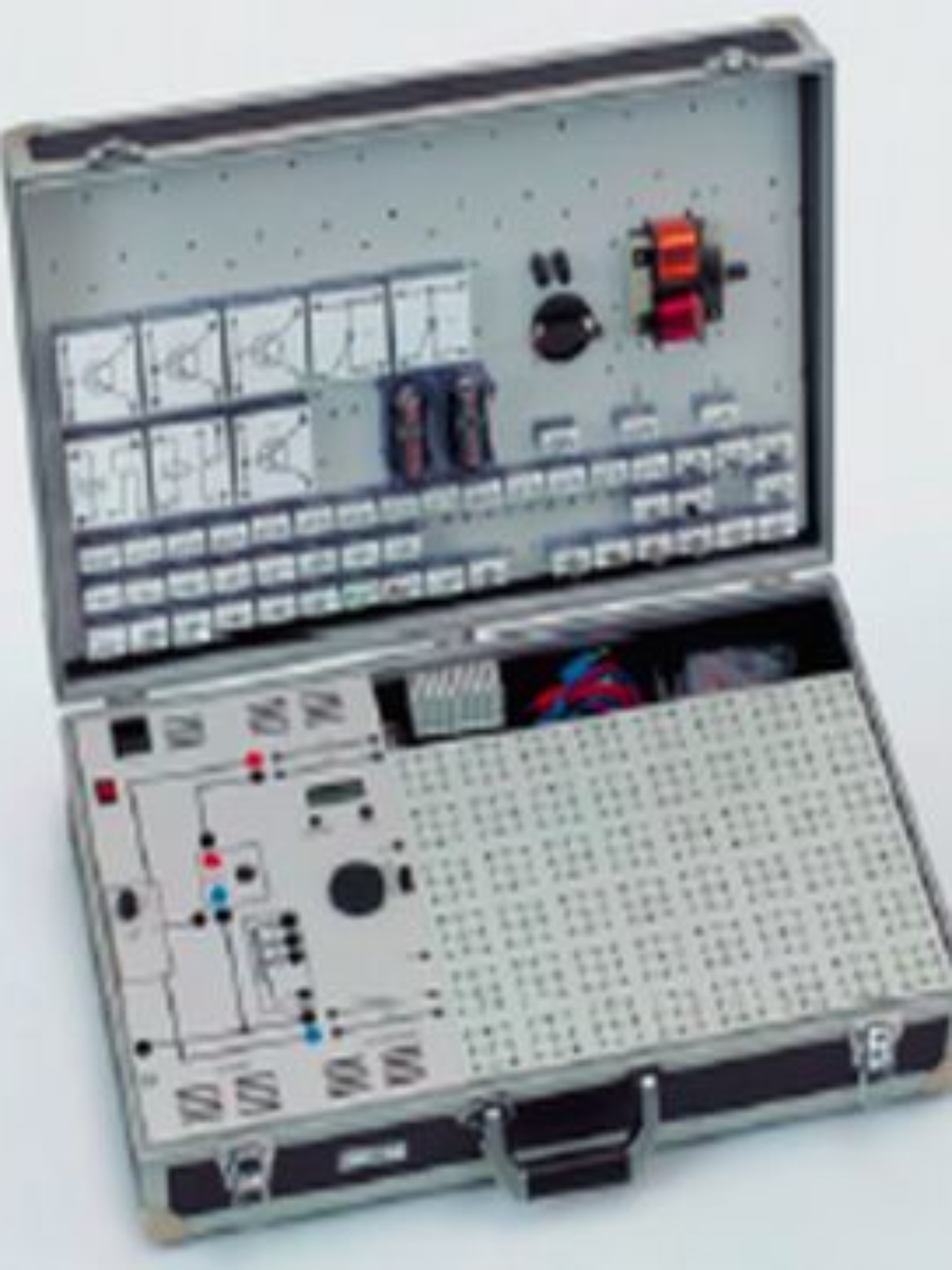
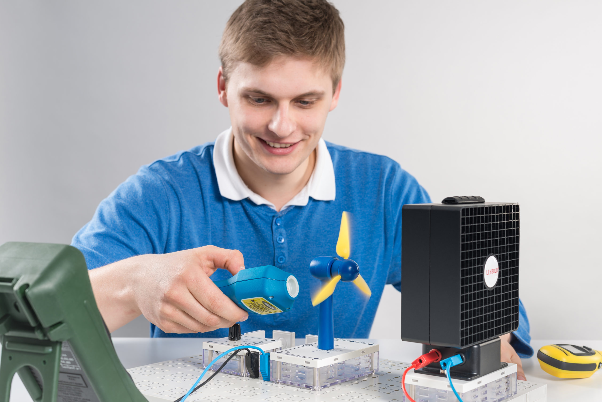
The LEYBOLD STE plug-in system is a tried and tested experimentation program for electrical engineering and automotive electronics. Experimentation literature in the form of instruction sheets are available for both students and teachers to assist in performing the experiments.
The printed symbols on the plug-in housing elements, connectors, and training panels provide the experiment set-ups with a circuit-like appearance. This facilitates knowledge transfer between the circuit diagrams in the textbooks and the circuitry being assembled and makes documenting the experiment findings easier and ultimately promotes circuit-based thinking, learning, and experimenting.
The STE elements come ready for use and are protected against external mechanical damage due to their electrical and electronic components encased in transparent housings. Thanks to the transparent bottom part the original component is visible.
The STE case is the storage solution which also serves as a student workstation. The cover can be used to accommodate various STE equipment sets and also assist in performing experiments in the classroom. The clearly configured storage design permits quick setup and a quick start to experimenting.
- 2 Mono cells 1.5 V
- 2 Plug-in battery holder
- 4 Light bulbs 4 V/0.16 W/E10
- 4 Light bulbs 12 V/3 W/E10
- 4 Light bulbs 12 V/1.2 W/E10
- 1 Glow lamp 110 V/E10
- 1 Bar magnet 60 X 13 X 5 mm
- 1 Rotary support for bar magnet
- 1 Resistor 10 ohm, 2 W
- 1 Resistor 47 ohm, 2 W
- 2 Resistors 100 ohm, 2 W
- 2 Resistors 200 ohm, 2 W
- 1 Resistor 330 ohm, 2 W
- 1 Resistor 470 ohm, 2 W
- 1 Resistor 1 kohm, 2 W
- 1 Resistor 2.2 kohm, 2 W
- 1 Resistor 4.7 kohm, 2 W
- 2 Resistors 10 kohm, 0.5 W
- 1 Resistor 22 kohm, 0.5 W
- 1 Resistor 47 kohm, 0.5 W
- 1 Resistor 220 kohm, 0.5 W
- 1 Potentiometer 220 ohm, 3 W
- 1 Variable resistor 10 kohm, 1 W
- 1 Variable resistor 47 kohm, 1 W
- 1 Variable resistor 470 kohm, 1 W
- 1 Photoresistor LDR 05
- 1 NTC-Resistor 2.2 kohm
- 1 PTC-Resistor 100 ohm
- 2 Capacitors 10 nF, 100 V
- 1 Capacitor 0.1 µF, 100 V
- 1 Capacitor 0.22 µF, 250 V
- 1 Capacitor 1 µF, 100 V
- 1 Capacitor 100 µF, 35 V
- 2 Capacitors 470 µF, 16 V
- 1 Ge diode AA 118
- 4 Si diodes 1N 4007
- 1 Z diode ZY 6.2
- 1 Light emit. diode green, LED 1, top
- 1 Light emit. diode red, LED 2, top
- 2 Transistors BD 137 (NPN), e.b
- 1 Transistor BD 138 (PNP), e.t.
- 1 Darlington transistor TIP 162
- 1 Thyristor TYN 1012
- 1 Lamp holder E10, lateral
- 4 Lamp holders E10, top
- 1 Pushbutton switch, single-pole, n.o.
- 1 Toggle switch, single-pole
- 1 Lampe current relay
- 1 Relay with single-pole change over switch
- 2 Clamping plugs
- 1 Iron wire 0.2 mm dia., 100 meters
- 1 Coil 500 turns
- 1 Coil 1000 turns
- 1 Transformer core, demountable
- Power supply: 230 VAC, 50/60 Hz
- 1 Case Large, equipped with:
-
- 1 Rastered socket panel DIN A3
- 1 AC/DC Stabilizer
- 1 Function generator 200 kHz
- 3 Sets of 10 Bridging Plugs
- 1 Connecting Lead 10 cm Red
- 1 Connecting Lead 10 cm Blue
- 3 Pair cables 50 cm, red/blue
- 1 Set of components as listed
- 1 User manual
- 1 Power cord
Dissectible Machines System - E2.2.7.10
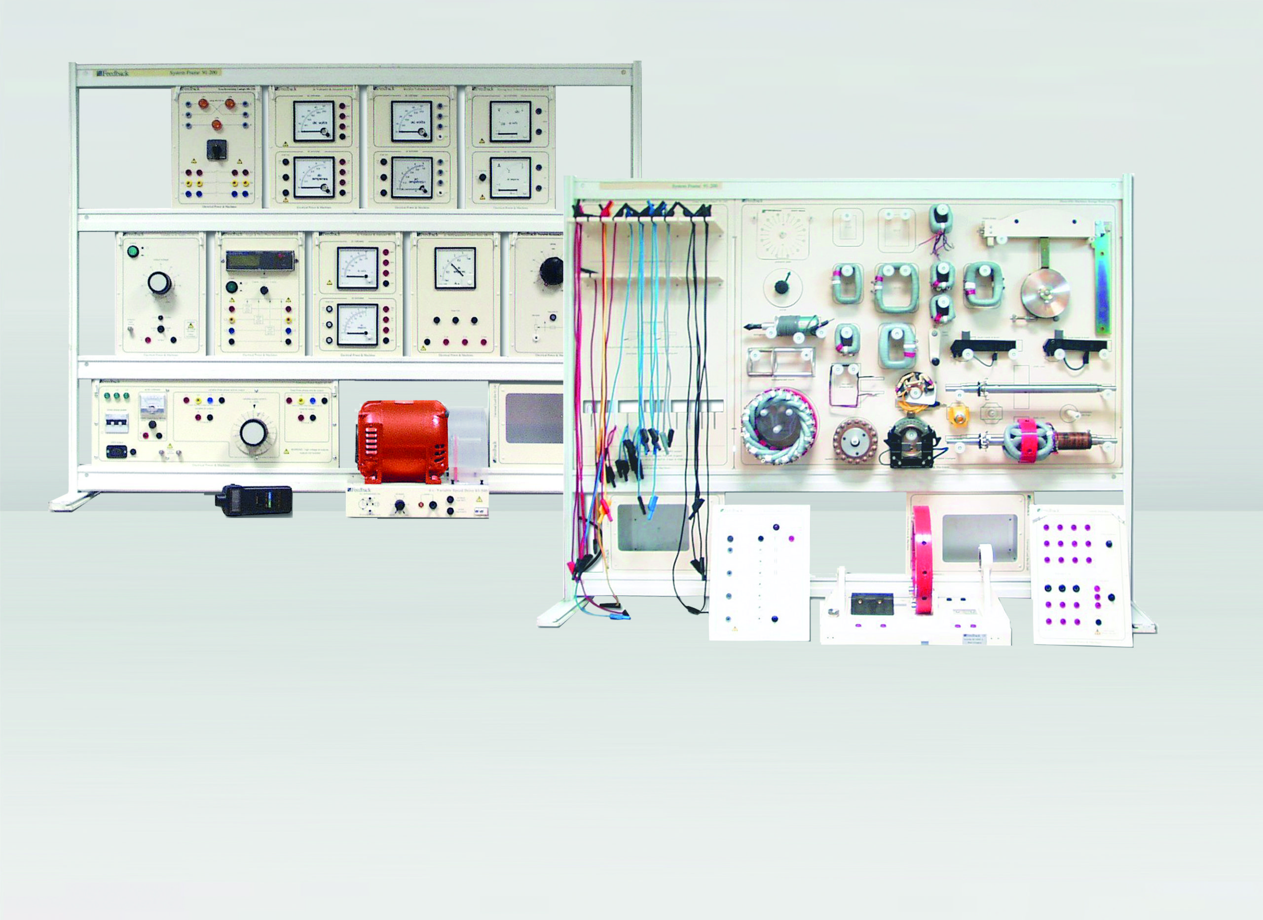
This trainer provides all the components to perform the full range of student assignments using the Dissectible Machine, which enables construction and investigation of different machine assemblies. The system is used to study a wide range of topics, from the principles of magnetic circuits and electrical machine theory through to three-phase synchronous machines.
The bench-top, free-standing frames divide the equipment into two distinct areas. One frame specifically holds all the component parts of the Dissectible Machine on an inventory control panel that also includes connecting lead storage and component storage for couplings. The second frame houses the workstation. It consists of a wide range of AC and DC meters, resistive and capacitive loads, and power supplies. The system provides a hands-on approach to the understanding of electrical machines principles.
- Complete training system comprising 2 panels
- First panel is to display & store components
- Second panel is the workstation (running & testing machines)
- More than 50 types of machine can be assembled
- Choice of conventional or virtual instruments
- Comprehensive theory & experimental manual, fully developed course curriculum
- Thorough construction & testing of electrical machines
- Machines construction from component parts
- Magnetic principles to three phase machines
- Conventional instrumentation pointer type & digital meters
- DC single phase & three phase motors & generators
- Protected supplies, meters & connecting leads
- Safety earthing system
- Easy benchtop installation
- Portable machine & system components
- Baseplate
- Frame ring
- Shaft
- Coupling
- Fixed & removable bearing housings
- Wound stator
- Squirrel cage rotor
- Hand crank
- Centrifugal switch
- Brush holders & brushes
- Commutator / slip rings
- Interpoles
- Armature poles & hub
- Field poles
- Armature, field & interpole coils
- Compound field coils
- Tools & hardware
The equipment includes demonstration experiments and student experiments in the laboratory. The experiments are carried out using a manual in printed or electronic form and are designed for a higher level of learning. The system can be supplemented by equipment for measuring, closed loop control, control, and electrical machines.
- Elementary AC & DC generators
- DC. series motor & generator
- DC shunt motor & generator
- DC compound motor & generator
- DC separately excited generator
- Single AC induction motor
- Squirrel cage, 2 pole & 4 pole
- Single phase AC series universal motor
- Single phase AC repulsion motor
- Single phase AC synchronous motor
- Generator, 2 pole & 4 pole
- Single phase AC generator, rotating field
- Single phase AC. generator, rotating armature
- Three phase AC induction motor, squirrel cage, 2 pole & 4 pole
- Three phase AC synchronous motor, 2 pole
- Three phase AC synchronous generator, 2 pole
- AC brushless generator
- Stepper motors
- Shaded pole induction motor
- Split field series motor
- Dynamic braking of a DC motor
- Power factor correction of AC motors
- Synchronisation
- Synchronous motor characteristics
- Pole-changing induction motor
- DC shunt motor faults
- 4 pole induction motor faults
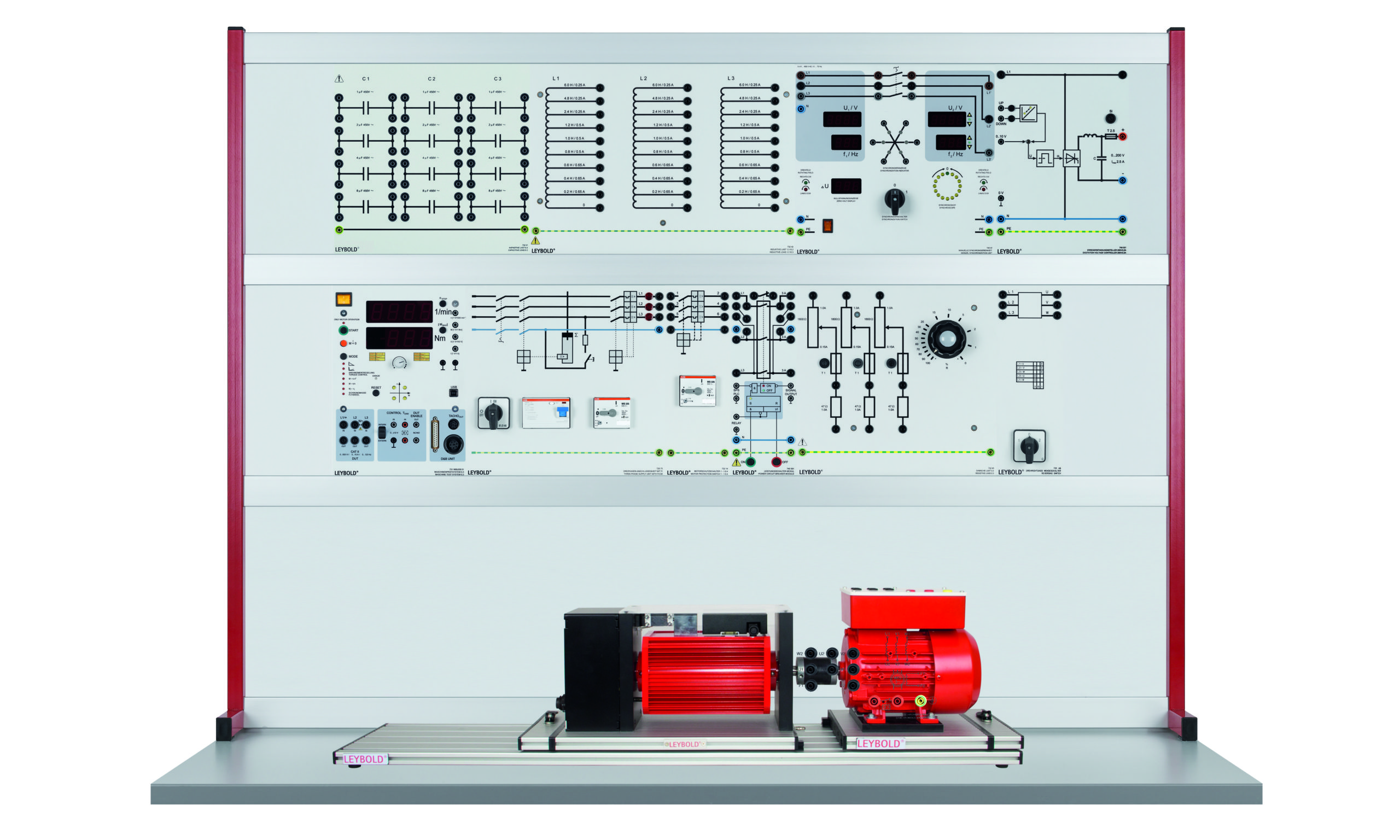
Synchronous Machine with Permanent Excitation IPM and Frequency Converter 0,3 - E2.2.6.1
The experiments are carried out using machines of industrial manufacture. All the test machines are equipped with a special base for attachment to the Machine test system 0.3. The system allows the characteristics of the machines under test to be recorded. Power for the machines under test is provided either directly from the mains or via special laboratory power supplies.
- Protective measures and electrical safety
- Setting up electrical machines and putting them into operation
- Use of starting circuits
- Assessment of electrical machine characteristics
The machine to be tested is an industrial frequency converter motor consisting of a four-pole asynchronous three-phase motor with a power rating of 0.55 kW including an integrated frequency converter. The motor and the converter are optimally fine-tuned to one another. The experiment investigates the features of the operating response in comparison to other types of machine without built-in power electronics. More advanced topics such as positioning control or non-linear load characteristics (winding machines, fans etc.) are investigated in E2.6 Servo technology.
- In order to protect against overheating, the stator windings of the test machines are equipped with temperature sensors
- Should overheating occur, the machine testing system automatically shuts down the machine under test, thus preventing any damage to it.
- The test machines are equipped with an educationally designed terminal board with the winding configuration printed on it.
- The ends of all the windings are connected to the terminal board and can be accessed via 4-mm safety sockets.
- Computer-supported acquisition of measurement data provides for meaningful measurement results.
The individual equipment set is equally suitable for student experiments in laboratories with low voltage supplies (400 V three-phase) and for setting up on a mobile trolley for demonstration by teachers in a classroom. The procedures for the experiments are provided in a printed manual.
The target group is made up of commercial apprentices and students of electrical machine construction. The course offers experiments at an intermediate level and also allows for the necessary insight into machine behaviour for scientific interpretation at undergraduate level.
- Design and function of a frequency converter controlled motor
- Operation with a power amplifier
- Run-up and operating characteristics
- How speed depends on frequency
- How speed depends on load: fan, pump, winding machine, flywheel
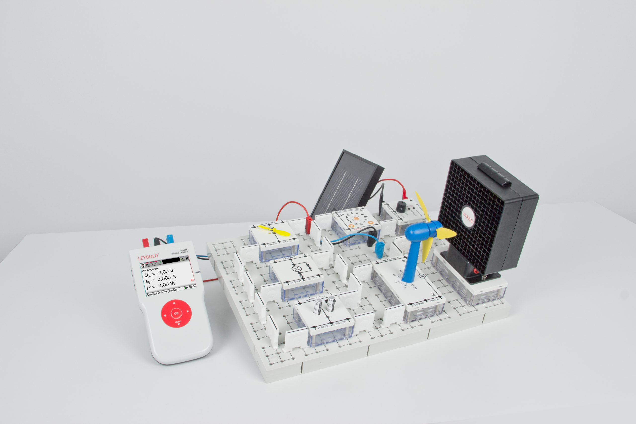
Smart Grid Experimental Case - 580 0400
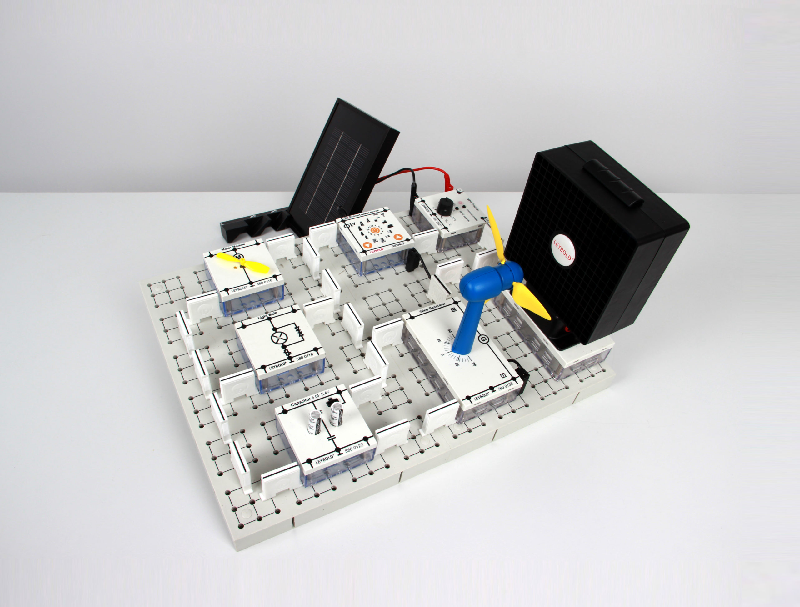
The increasing proportion of renewable energy sources in power generation such as Photovoltaic and wind turbines in combination with conventional power plants requires a completely new (intelligent or "smart") network management.
LEYBOLD STE "Smart Grid" provides vivid experiments on the subject: volatile production operation of the conventional power grid, problems with the integration of renewable energy, and operation of "smart" solutions. The interpretation of the obtained readings is an interesting task.
The experimental manual includes many experiments about the Smart Grid:
- Basic experiments on photovoltaic
- Basic experiments on wind power
- Basic experiments on energy storage systems
- Building supplied by a power plant, a photovoltaic system and an energy store
- Scenario experiments (power fluctuations, load changes, weather dependencies)
- Complete set with more than 20 components STE about smart grid.
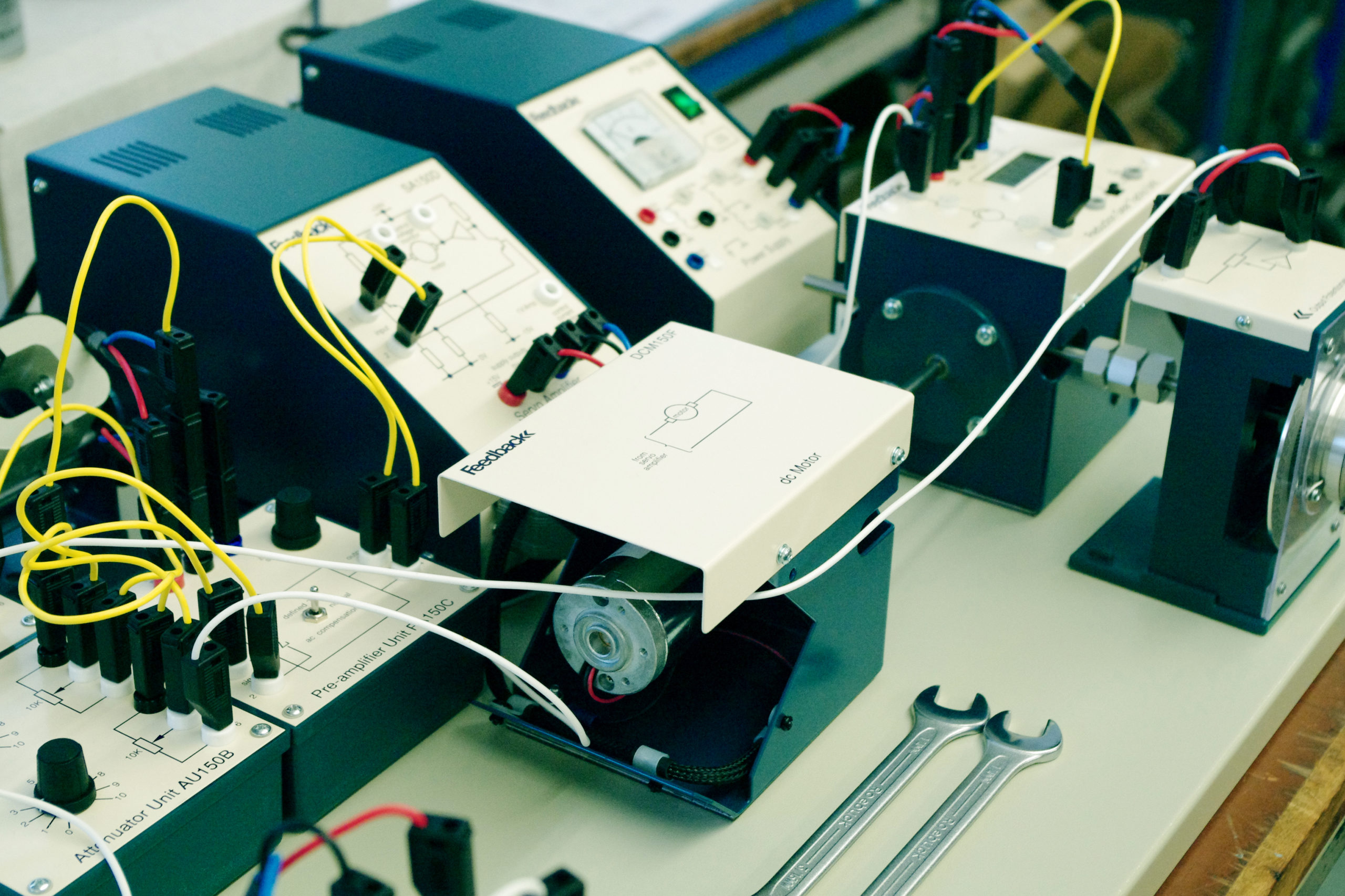
Modular Servo Systems - E6.3.5.13
The modular servo system enables students to study the theory and practice of automatic control systems. It illustrates modern circuit and constructional techniques.The system is modular and, therefore, versatile. Each unit is fitted with a magnetic base which holds the unit to the plastic coated steel base plate, irrespective of the angle at which the base plate is positioned.
Individual units may be so arranged to create operating block schematic systems and interconnections between the units are made by jumper leads terminated in 4 mm stackable plugs. The modular concept of the MS150 system permits the study of individual units and also, by combination, the investigation and performance testing of complete systems. A series of instructional manuals is supplied to provide comprehensive coverage of servo system theory and assignments.
The equipment set incorporates student experiments which can be carried out in a laboratory safely using extra-low voltage. Experiment instructions are contained in a manual in either printed or digital form. This training program is made for the advanced training study programs at applied technology universities and technical universities. Knowledge of classic control engineering is a prerequisite.
- Operational amplifiers
- Motor speed characteristics
- d.c. error channel
- Simple position control
- Closed-loop position control
- Simple speed control
- Deadband & step response
- Velocity feedback
- Analysis of simple speed control with speed response
- Position response
- Closed-loop frequency response
- Identification of motor time constants
- Identification of velocity error constant
- Frequency and transient response
- Measurement of following error
- Stability considerations & the use of lead, lag & combined networks
- Tachogenerator feedback &the effect on system performance
- Acceleration feedback
- Linearisation of systems
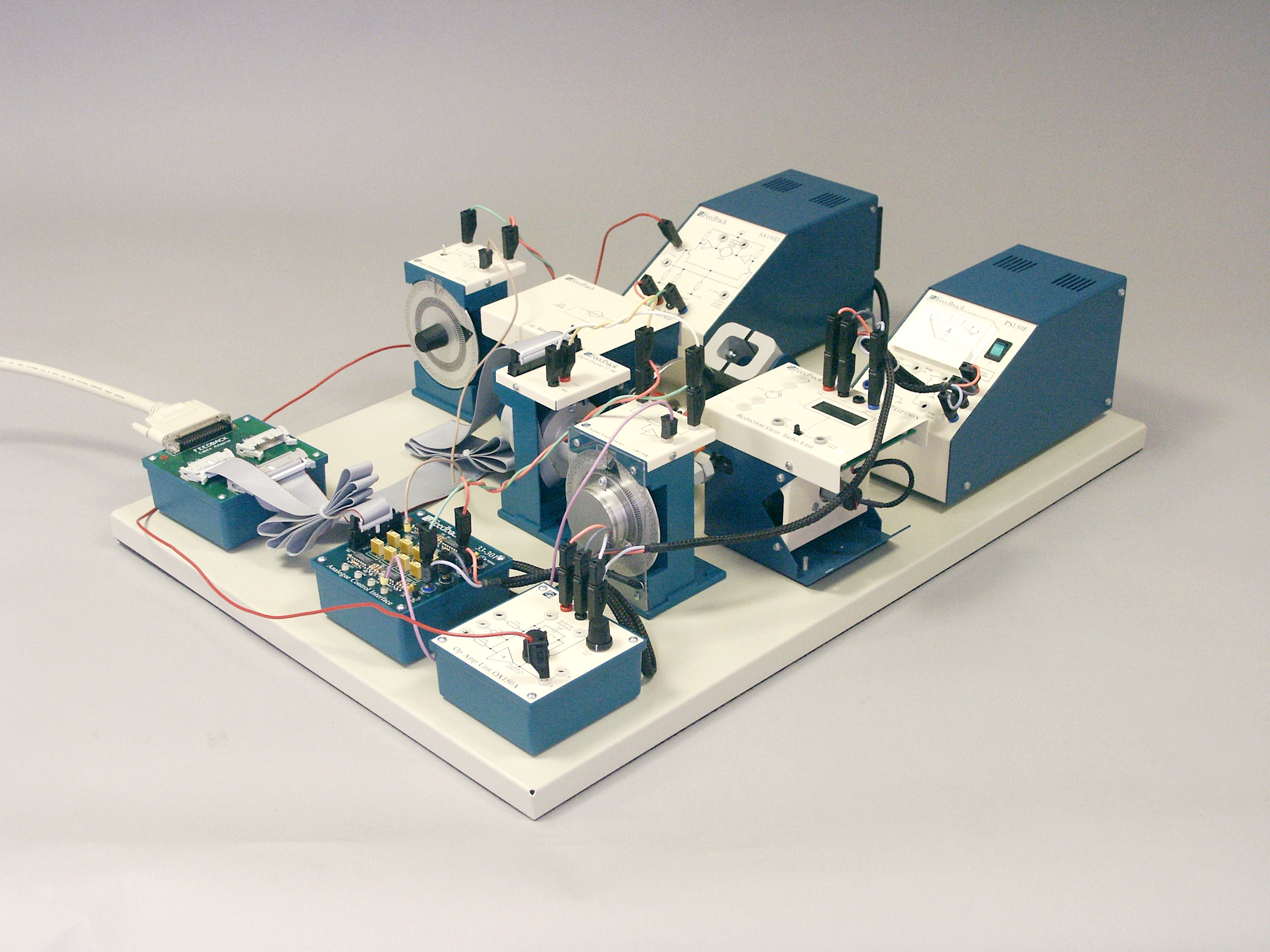
Precision Modular Control Workshop - E6.3.5.15
The Precision Modular Servo Workshop provides a rapid and direct path from control system design to hardware implementation. The resolution and accuracy of the system and the consistency of its performance makes the Precision Modular Servo Workshop ideal for serious study of digital linear servo control systems.
As well as allowing study of digital control, the Precision Modular Servo Workshop also provides a complete introduction to servos, from fundamental studies of analogue servos through to full, real-time digital control. It is fully supported with laboratory assignments which have been designed to give students a full understanding of the control paths within the equipment.
The equipment set incorporates student experiments which can be carried out in a laboratory safely using extra-low voltage. Experiment instructions are contained in a manual in either printed or digital form.
A MATLAB™ license is required for this trial and is not included in the scope of delivery. The equipment can require additional software modules.
This training program is made for the advanced training study programs at applied technology universities and technical universities. Knowledge of classic control engineering is a prerequisite.
- Precision modular servo (PMS)
- Testing the d.c. motor
- PMS model identification - static friction compensation, model 1 & 2 identification
- PMS position control - PID control of motor position, real-time PID control of motor position, position tracking
- PMS control, under variable control conditions - simple gain scheduling algorithm, gain scheduling
- PMS set-up control - plant control, PID controller, PMS velocity control, PID control of motor velocity, real-time PID control of motor velocity, control signal saturation, anti-wind up design, anti-wind up for PMS
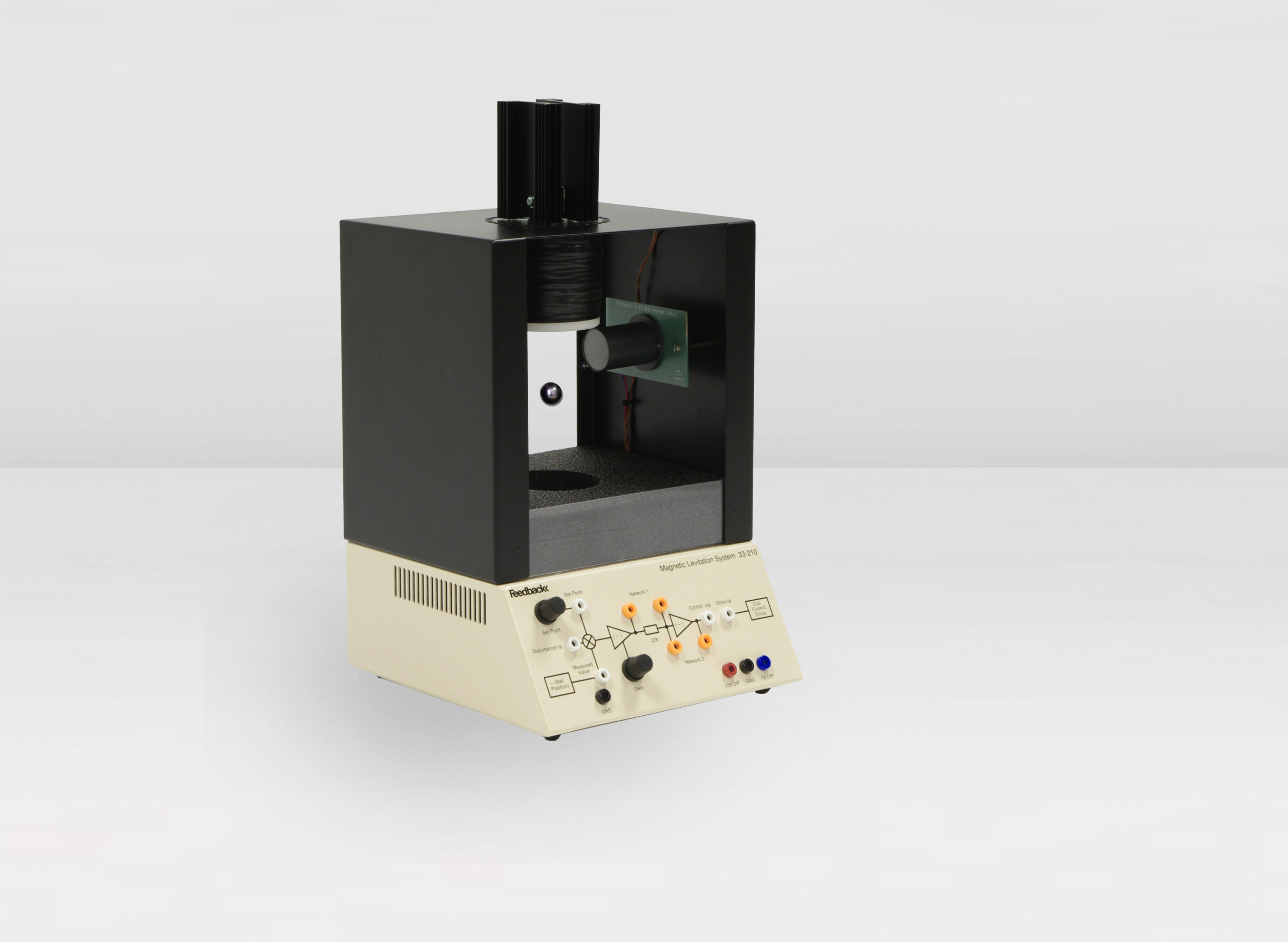
Magnetic Levitation - E6.3.5.14
This classic magnetic levitation control problem is now presented in a new and innovative form. A 25mm diameter, hollow steel sphere is suspended in space with visually-appealing results and convenient time constants. Both analogue & digital control solutions are implemented.
Convenient sockets on the enclosure panel allow for quick changes of analogue controller gain and compensation components.
The equipment is self-contained in analogue mode, with built-in power supply. In the digital mode, the system operates within a MATLAB/LabVIEW environment (MATLAB™/LabVIEW™ not supplied) which allows the system parameters to be determined and the system to be modeled.
The equipment set incorporates student experiments which can be carried out in a laboratory safely using extra-low voltage. Experiment instructions are contained in a manual in either printed or digital form.
A MATLAB™ license is required for this trial and is not included in the scope of delivery. The equipment can require additional software modules.
This training program is made for the advanced training study programs at applied technology universities and technical universities. Knowledge of classic control engineering is a prerequisite.
Analogue Operation
- Non-linear models
- Unstable systems
- Linearisation about an operating point
- Infra-red sensor characteristics
- Lead-lag compensation
- Perturbation sensitivity
- PD control
Digital Operation
- Non-linear models
- Unstable systems
- Linearisation about an operating point
- A/D & D/A conversion
- State space PD control
- PID control
- Calibration
- Regulation & tracking control
Static Converter Drives & Induction Machines - E2.5.3.1
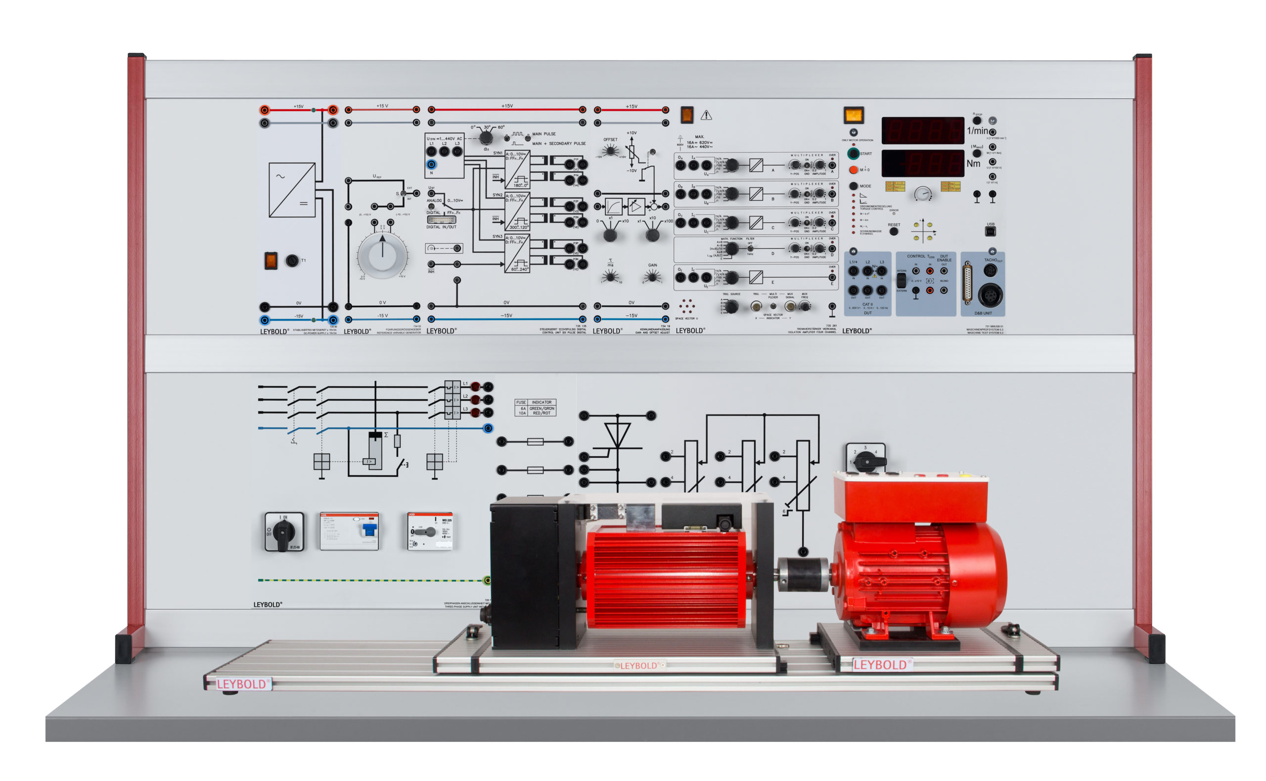
The power electronics part of this lab practical uses training panels. The electrical machine employed is an industrial machine on a base, whereby the characteristics of the machine can be determined using the Machine test system 0.3. Power is supplied to the machine under test via a static converter, which obtains its power from the (three-phase) mains network.
This equipment set allows experiments on how the speed of asynchronous (induction) machines can be modified using line-commutated static converters. The speed of the machine depends on the stator voltage and rotor impedance and can be adjusted in the experiment by changing these two variables.
As well as putting the machine into operation and setting its parameters, the main thing considered is the change in the response of the machine. This involves recording load characteristics and determining key parameters. Addition of a PID controller allows the experiment set-ups to be enhanced into variable-speed drives with closed-loop speed control.
Students work in the power engineering lab with mains voltage. Experiments procedures are contained in a printed manual. The experiments are designed for intermediate and advanced levels.
- Protective measures and electrical safety
- Set-up of power generating systems according to circuit diagrams
- Putting electrical drives into operation
- Recording of load characteristics with various operating parameters
- Achieving skills in measuring electrical machines
- Automatic speed control for an asynchronous (induction) machine
- Drives using motors with slip-ring rotors and three-phase power controllers
- Drives using motors with slip-ring rotors and pulse-controlled rotor impedance
- Drives using motors with slip-ring rotors and static converter cascades
All images supplied by and used with permission of copyright holder: © LEYBOLD /LD DIDACTIC GmbH


