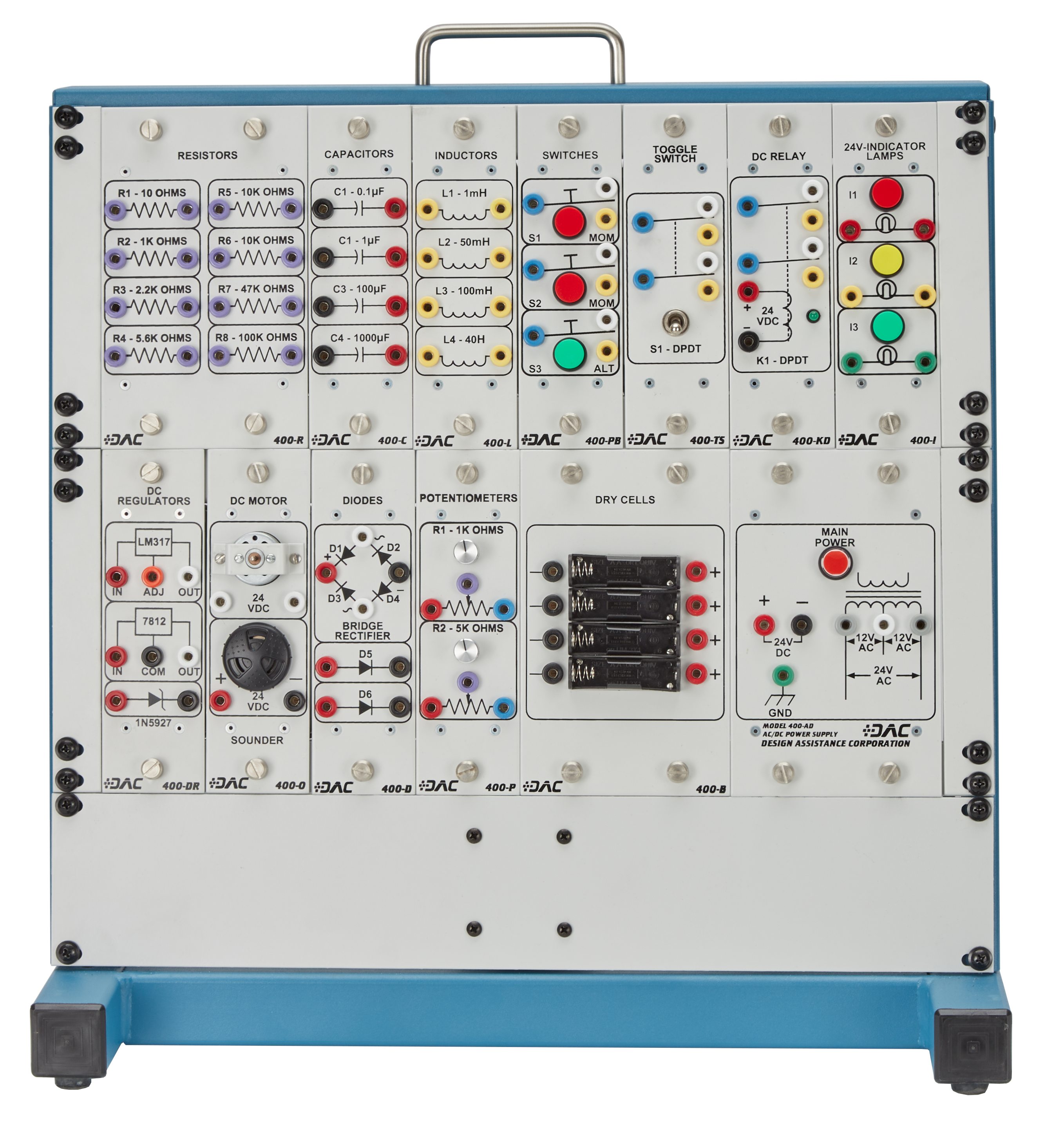
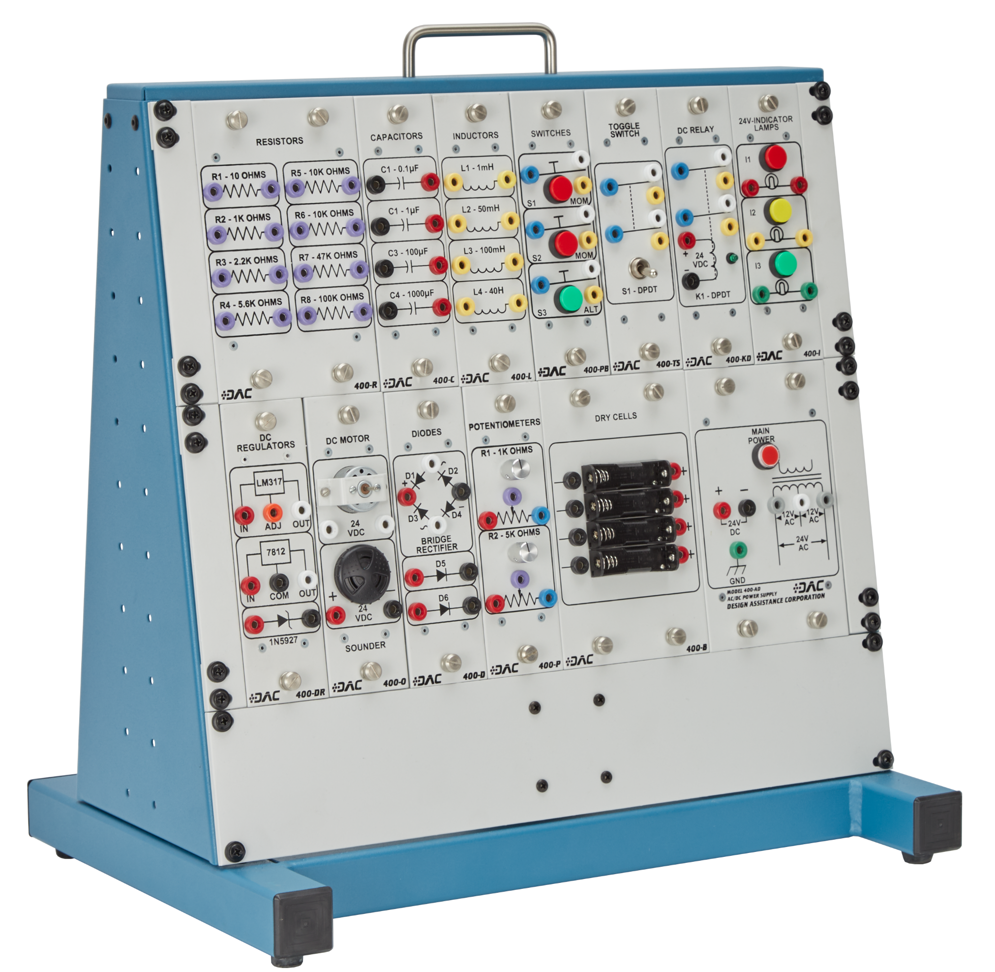
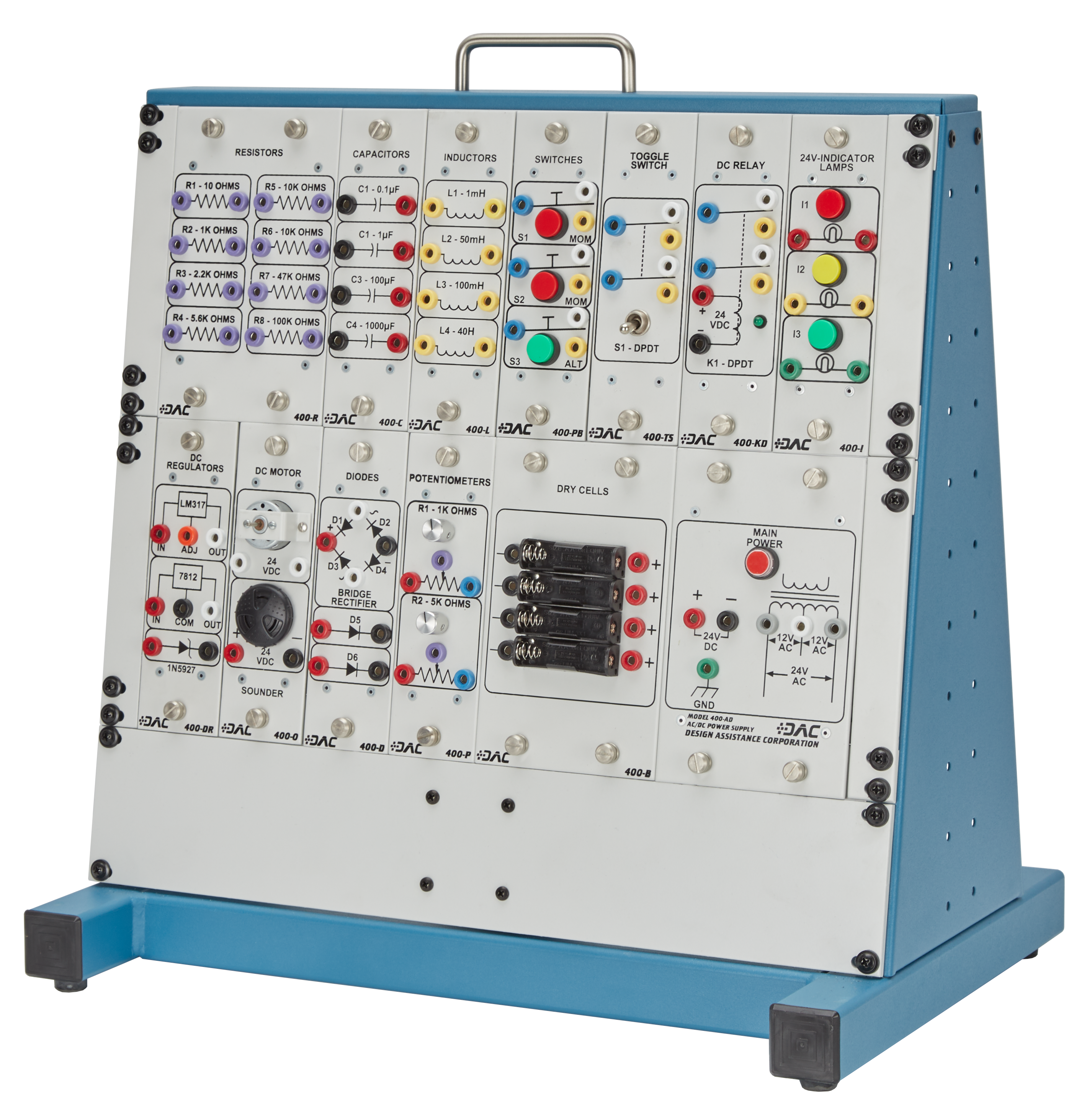
- Modular panel and rack/frame system facilitating alternate module locations and allowing for system expansion in the future
- Each component panel assembly includes: a 1/8" aluminum panel face; epoxy silk-screened component nomenclature and symbols; riveted, 16-gauge, formed-steel enclosures; powder coating and instructor fault switches
- Provision for mounting of system on standard DAC mounting structures, or any standard 19" rack system
- On-board circuit breaker, internal power supply, and transformer, creating working voltages of 24VAC center tapped, or 24VDC
- Primary electrical components over-sized to improve durability and provide protection from over-current accidents
- Crating for shipment via motor freight
DISCLAIMER: Product Dimensions are approximate. Shipping Dimensions and Weights are for directional use only and may change based on manufacturer variables. For the most accurate Shipping Dimensions and Weights, please contact the manufacturer.
- Product Dimensions
(L x W x H)
18 1/8in. x 14in. x 17 1/2in. (460 x 355 x 444 mm)
25 lbs. (12 kg) approximate
110/220 VAC, 50/60 Hz
- Loose component kit including: (2) bar magnets, (1) component storage box, (1) magnetic reed switch, (1) nail, (1) spool of bell wire, (1) sealed box of iron filings, (1) D cell holder, (1) compass, (1) 6" acrylic rod, (1) rubbing cloth, (1) 6" wood dowel, (1) solderless breadboard (2" x 3"), (2) NPN transistors, (2) PNP Transistors, and (10) assorted resistors
- Banana plug patch cords
- Use/Activity Guide
- Textbook, Electricity & Electronics, 10th Edition (Gerrish, Dugger, & Roberts)
- #400-500 - Use/Activity Guide (additional copies)
- #410-001 - Digital Multimeter
- #600-102 - Sweep/Function Generator
- #400-113 - Oscilloscope
Topics include:
- Introduction to the DAC #400 Electricity Fundamentals Trainer
- Use of Digital Multimeter
- Calculation and Measurement of Voltages in Series and Parallel
- Identification of Resistors Values Using the Resistor Color Code
- Calculation and Measurement of Resistance in Series
- Calculation and Measurement of Resistance in Parallel
- Calculation and Measurement of Resistance in Series-Parallel
- Calculation and Measurement of Voltages, Current, and Power in a Series DC Circuit
- Calculation and Measurement of Voltages, Currents, and Power in a Parallel DC Circuit
- Calculation and Measurement of Voltages, Currents, and Power in a Series-Parallel DC Circuit
- Use of a Potentiometer to Vary Circuit Voltage
- Use of a Rheostat to Vary circuit Current
- Troubleshooting a Series DC Circuit Using a Voltmeter
- Troubleshooting a Series-Parallel Circuit Using a Voltmeter
- Observation of Magnetic Lines of Force
- Observation of Induced Magnetism
- Use of Oscilloscope
- Use of the Function Generator
- Observation of the Voltage and Current in Inductive DC Circuits
- Determination and Observation of the Time Constant of an Inductive DC Circuit
- Observation of the Voltage and Current in Capacitive DC Circuits
- Determination and Observation of the Time Constant of Capacitive DC Circuits
- Calculation and Measurement of the AC Parameters
- Observation of the Voltage and Current in Resistive AC Circuits
- Observation of the Voltage and Current in AC Circuits with Resistance and Inductance
- Observation of the Voltage and Current in AC Circuits with Resistance and Capacitive
- Calculation and Measurement of the Voltages, Currents, and Power in Series RLC AC Circuits
- Calculation and Measurement of the Voltages, Currents, and Power in Parallel RLC AC Circuits
- Calculation and Measurement of the Voltages, Currents, and Power in Series-Parallel RLC AC Circuits
- Use of RC Circuits in Pulse Shaping
- Design and Operation of Series and Parallel Resonant Circuits
- Determination of the Turns-Ratio of a Transformer
- Plotting the Characteristic Curve of a Diode
- Operation of a Clipper Circuit
- Operation of a DC Resistor Circuit
- Operation of an Amplitude Discriminator Circuit
- Operation of a Half-Wave Rectifier
- Operation of a Full-Wave Rectifier
- Operation of the Full-Wave bridge Rectifier
- Use of the Power Supply Filter
- Observation and Calculation of Voltage Regulation
- Operation of the Voltage Doubler Circuit


