Control Valve Characteristics Training System

Model: 618-000

Process control systems maintain precise control of liquid and gas variables, such as liquid level, flow rate, pressure, temperature, and pH level. These multifaceted systems are a critical part of major industries like power generation, refineries, petrochemicals, chemical manufacturing, pharmaceuticals, biotechnology, and food processing and bottling.

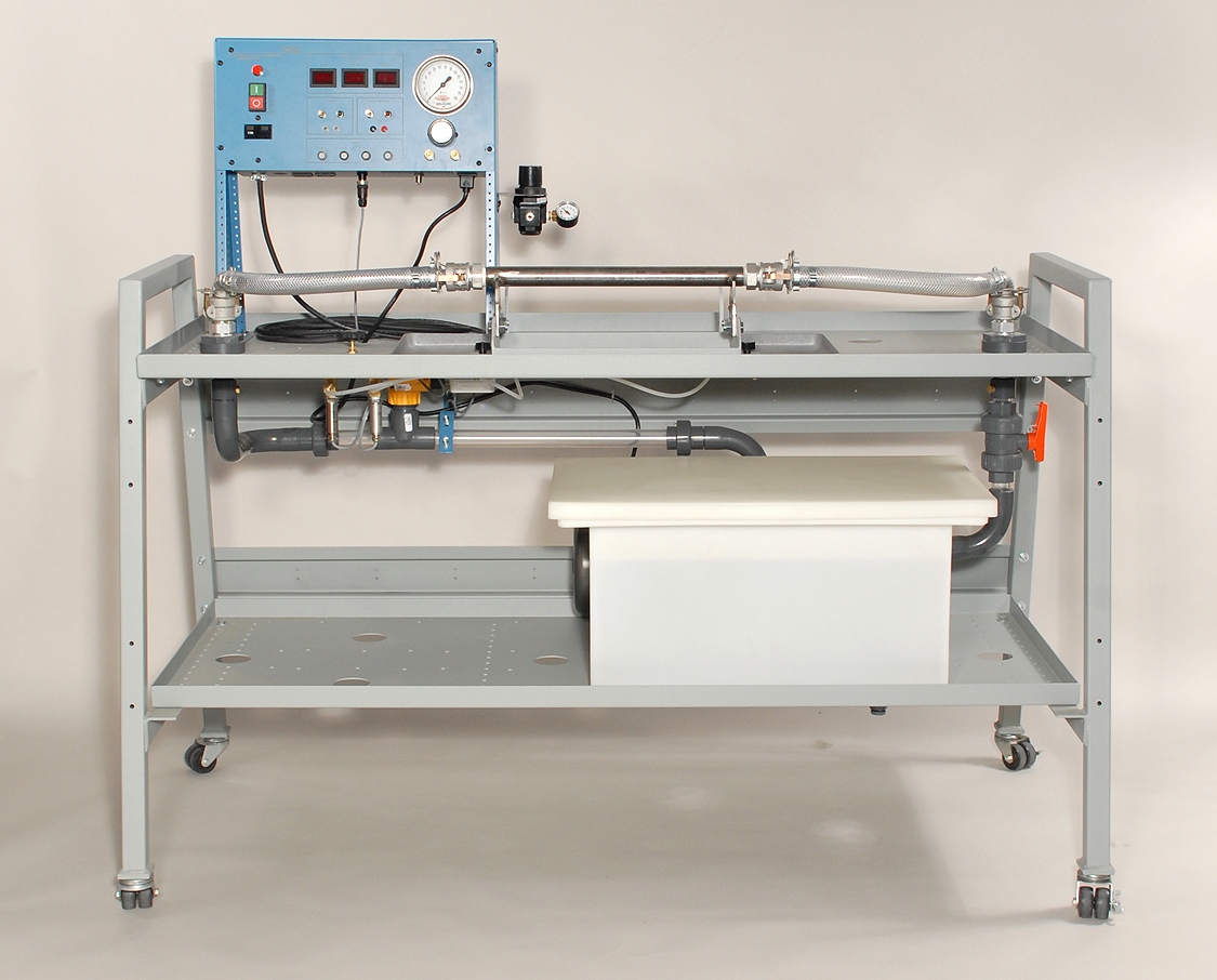
DAC Worldwide’s Control Valve Characteristics Training System (618-000) is a working fluid process system, allowing for hands-on training relating to the design, calibration, and testing of common control valves used in industry. The system includes provision for mounting control valves of different designs, including diaphragm-type valves, by a variety of manufacturers.

Study Control Valve Characteristics with Hands-On Training System

A magnetic flow meter and two pressure sensors are provided in order to demonstrate performance at different flow rates using multiple valve plug and trim designs. Field calibration of valves and positioners can be accomplished using a high-quality regulator and test gauge.

With optional and/or user-supplied equipment the Control Valve Characteristics Training System can be used to create basic process loops incorporating flow control.

The system requires the #600-006A Economy Standard Test and Calibration Equipment Package and #600-066 PID Controller and I/P Converter Panel. The system also requires valves in order to operate. These valves can be purchased from DAC Worldwide or donated from industry. It includes a workstation, caster set, two digital pressure displays, digital flow display, pilot light, GFI circuit protection, test gauge, precision regulator, service air regulator, magnetic flow meter, and centrifugal pump.

  • Service requirements: electric - 220/50-60/1; water source.
  • Welded steel frame workstation, using 14-gauge, 1-1/2" x 1-1/2" tube and incorporating two, 14-gauge support shelves.
  • Four (4) casters, two with locks.
  • Clear, 1" diameter, PVC piping and fittings throughout.
  • Primary reservoir, 15 gallon capacity.
  • Power/meter module including 19" rack panel, enclosure, and 16-gauge steel support structure.
  • Panel-mounted components, including two digital pressure displays, digital flow display, pilot light, on/off switch, pump control with provision for external control via relays, GFI circuit protection, fuses, test gauge (0-30 psig), precision regulator, quick-connect air fittings, and electrical service outlets.
  • Enclosure-mounted, supplemental, 4-20 mA flow meter connections.
  • Service air regulator and quick disconnects.
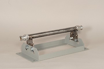
  • Industrial hose connectors and hose allowing for attachment of demonstration valves.
  • Quick-disconnect tubing fittings allowing for attachment of instruments.
  • Magnetic flow meter, monitoring upstream flow.
  • Throttling ball valve on downstream flow.
  • Centrifugal pump, 1 HP, with inlet strainer.
  • Provision for mounting optional rack-mounted instruments.
  • High-durability, powder-coated surfaces throughout.
  • 100 ¼”-diameter instrument connection tubing of two colors.
  • Six (6) quick-disconnect nipples.
  • Six (6) tubing tees.
  • Six (6) tubing couplers.
  • Use/Exercise Guide.
  • Crating for shipment via motor freight.

DISCLAIMER: Product Dimensions are approximate. Shipping Dimensions and Weights are for directional use only and may change based on manufacturer variables. For the most accurate Shipping Dimensions and Weights, please contact the manufacturer.

  • Product Dimensions
    (L x W x H)
    63in x 24in x 50in (1600 x 600 x 1275 mm)
    255 lbs. (116 kg)
  • Shipping Dimensions
    (L x W x H)
    67in x 37in x 64in (1701 x 939 x 1625 mm)
    523 lbs. (237 kg)
  • #600-006A - Test and Calibration Package, Hand-Held, Economy (required)
  • #600-066 - Supplemental PID controller and I/P converter panel (required)
  • #910 - Rolling Rack Assembly
  • #600-051 - Strip chart recorder, 2-pen (Yokogawa, SR 1000) (additional)
  • #618-001 - Control valve demonstration set, 3-piece
  • #618-500 - Additional Use/Exercise Guide
  • #618-CTL - Quick-Start Control Package, including: #618-000, #618-001, #600-066
  • #940-001 - Control Module Base Assembly
  • #940F - Control Module Assembly Frame (for supplemental panels)
TOP